安装一些功能包 Install some packages:
sudo apt install ros-melodic-joint-state-publisher-gui
sudo apt install ros-melodic-ros-control
sudo apt install ros-melodic-ros-controllers
sudo apt install ros-melodic-gmapping
sudo apt install ros-melodic-ackermann-msgs
sudo apt install ros-melodic-navigation
sudo apt install ros-melodic-teb-local-planner
将三个功能包放进工作空间src目录下,进行编译
cp /three packages /***_ws/src
cd ..
catkin_make
source devel/setup.bash
roslaunch racebot_gazebo racebot.launch

roslaunch racebot_gazebo gmapping.launch
roslaunch racebot_gazebo tianracer.launch

roslaunch racebot_gazebo gmapping.launch
将鼠标点击键盘控制窗口,即可控制小车运动进行建图。Click the mouse on the keyboard control window, you can control the movement of the car to build a map.
roslaunch racebot_gazebo tianracer.launch

roslaunch racebot_gazebo navigation.launch
roslaunch racebot_gazebo teb_demo.launch
roslaunch racebot_gazebo teb_demo.launch
roslaunch racebot_gazebo racebot.launch

roslaunch racebot_gazebo slam_navi.launch
roslaunch racebot_gazebo tianracer.launch

roslaunch racebot_gazebo slam_navi.launch
小车来之不易,且容易损坏。如果有的小组暂时没有ROS车或者ROS车暂时损坏了该怎么办呢,大道至简,我们可以搭建一个gazebo下的仿真环境来提前模拟代码或比赛情况。
首先,是小车本体,我们可以用一个典型的ros小车来仿真。这个有现成的,而且还带相机和激光雷达。感谢大佬的开源。 然后是world地图的建立,包括红蓝锥筒模型和黄线部分,还有一个重点是锥筒的摆放。因此,事情可以分为三部分:
- 锥筒模型,黄线模型
- 相对位置读取
- 模型自动摆放到gzebo中
在gazebo中有现成的锥筒模型,我们只需要改一下贴图就行了。这里我们就需要知道关于gazebo模型的组成了:模型文件夹下包括: ![[Pasted image 20241112205438.png]] 通过,观察config文件可以看出,config文件加载sdf文件,然后,sdf文件加载dae文件。然后,我们就可以在dae文件中看到加载的图片。我们就可以更改里面的图片来更换锥筒的贴图。
gazebo中黄色线条,我选择了使用黄色原点,通过密集的点组成黄色线条。主要是右边黄色半圆环的显示。
根据规则中的地图来摆放模型,如果直接手摆放的话,其中弧线的部分会很难摆放。由于,规则上的图有很明显的颜色和形状特征(红色或蓝色的圆形和黄色的线条),因此,我们选择使用opencv读取地图中相应位置坐标并转换成仿真world下的坐标。
#读取图片
image = cv2.imread('map.png')
height, width, _ = image.shape
#转换为hsv颜色空间
hsv_image = cv2.cvtColor(image, cv2.COLOR_BGR2HSV)
#定义蓝色和红色的HSV范围
lower_blue = np.array([100, 50, 50])
upper_blue = np.array([130, 255, 255])

lower_red1 = np.array([0, 50, 50])
upper_red1 = np.array([10, 255, 255])
lower_red2 = np.array([160, 50, 50])
upper_red2 = np.array([180, 255, 255])
#创建掩膜
blue_mask = cv2.inRange(hsv_image, lower_blue, upper_blue)
red_mask1 = cv2.inRange(hsv_image, lower_red1, upper_red1)
red_mask2 = cv2.inRange(hsv_image, lower_red2, upper_red2)
red_mask = cv2.bitwise_or(red_mask1, red_mask2)
#形态学处理
#使用闭运算(`cv2.MORPH_CLOSE`)去除掩膜中的小空洞,改善蓝色和红色区域的连通性。
kernel = cv2.getStructuringElement(cv2.MORPH_ELLIPSE, (3, 3))
blue_mask = cv2.morphologyEx(blue_mask, cv2.MORPH_CLOSE, kernel)
red_mask = cv2.morphologyEx(red_mask, cv2.MORPH_CLOSE, kernel)
#轮廓检测
#使用 `cv2.findContours` 函数检测蓝色和红色区域的轮廓
blue_contours, _ = cv2.findContours(blue_mask, cv2.RETR_EXTERNAL, cv2.CHAIN_APPROX_SIMPLE)
red_contours, _ = cv2.findContours(red_mask, cv2.RETR_EXTERNAL, cv2.CHAIN_APPROX_SIMPLE)
#计算圆度并筛选
#- 计算每个轮廓的面积和周长,利用圆度公式判断是否是圆形(`circularity > circularity_threshold`)。
- 对满足条件的圆圈,使用 `cv2.minEnclosingCircle` 得到最小外接圆,计算圆心坐标。
for contour in blue_contours:
    area = cv2.contourArea(contour)
    perimeter = cv2.arcLength(contour, True)
    if area > min_contour_area and perimeter > 0:
        circularity = 4 * np.pi * (area / (perimeter * perimeter))
        if circularity > circularity_threshold:
            (x, y), radius = cv2.minEnclosingCircle(contour)
            # 标记蓝色圆心

for contour in red_contours:
    area = cv2.contourArea(contour)
    perimeter = cv2.arcLength(contour, True)
    if area > min_contour_area and perimeter > 0:
        circularity = 4 * np.pi * (area / (perimeter * perimeter))
        if circularity > circularity_threshold:
            (x, y), radius = cv2.minEnclosingCircle(contour)
            # 标记红色圆心
#标记圆心
cv2.circle(blank_image, center, 5, (255, 0, 0), -1)  # 蓝色圆心
cv2.circle(blank_image, center, 5, (0, 0, 255), -1)  # 红色圆心
这段代码的核心思路是:
- 转换颜色空间为HSV,定义蓝色和红色的HSV范围;
- 提取对应颜色的区域并进行形态学处理;
- 检测轮廓并根据圆度判断圆形;
- 在图像上标记圆圈中心。
这种方法能有效提取图像中的蓝色和红色圆圈,并计算它们相对于图像中心的相对坐标。
在gazebo中我们可以通过调用特点的服务来自动的通过代码摆放特点的模型到指定坐标
#!/usr/bin/env python3


import rospy

from gazebo_msgs.srv import SpawnModel

from geometry_msgs.msg import Pose


def spawn_model():

# 初始化ROS节点

rospy.init_node('spawn_model_node')


# 等待服务可用

rospy.wait_for_service('/gazebo/spawn_sdf_model')


try:

# 创建服务代理

spawn_model_service = rospy.ServiceProxy('/gazebo/spawn_sdf_model', SpawnModel)


# 读取SDF模型

with open("src/PutModel/model/construction_cone_red/model.sdf", "r") as f:

model_xml = f.read()


# 设置模型的位置

model_pose = Pose()

model_pose.position.x = 1.0 # 设置X坐标

model_pose.position.y = 0.0 # 设置Y坐标

model_pose.position.z = 0.0 # 设置Z坐标

model_pose.orientation.w = 1.0 # 默认方向


# 调用服务生成模型

spawn_model_service("my_model", model_xml, "", model_pose, "world")

rospy.loginfo("Model spawned successfully.")


except rospy.ServiceException as e:

rospy.logerr("Service call failed: %s" % e)


if __name__ == '__main__':

spawn_model()
这段代码主要就是,调用gazebo服务,放置物体
import cv2
import numpy as np
import rospy
import math
from pathlib import Path
from typing import List, Tuple, Dict, Optional
from gazebo_msgs.srv import SpawnModel
from geometry_msgs.msg import Pose

class ColorDetector:
    def __init__(self, config: Optional[Dict] = None):
        # 初始化颜色坐标列表
        self.red_coords: List[Tuple[int, int]] = []
        self.blue_coords: List[Tuple[int, int]] = []
        self.yellow_coords: List[Tuple[int, int]] = []
        self.image: Optional[np.ndarray] = None
        self.scale_factor: float = 0.0246  # 缩放因子,用于将像素坐标转换为世界坐标

        # 默认配置,可通过传入config参数覆盖
        self.CONFIG = config or {
            'grid_size': 50,
            'min_contour_area': 50,
            'circularity_threshold': 0,
            'line_thickness': 1,
            'marker_size': 5
        }

    def read_image(self, image_path: str) -> None:
        # 读取图像文件
        self.image = cv2.imread(image_path)
        if self.image is None:
            raise ValueError(f"无法读取图像文件: {image_path}")

    def create_grid(self, height: int, width: int) -> np.ndarray:
        # 创建一个带网格的空白图像
        blank_image = np.ones((height, width, 3), np.uint8) * 255
        for x in range(0, width, self.CONFIG['grid_size']):
            cv2.line(blank_image, (x, 0), (x, height), (0, 0, 0), self.CONFIG['line_thickness'])
        for y in range(0, height, self.CONFIG['grid_size']):
            cv2.line(blank_image, (0, y), (width, y), (0, 0, 0), self.CONFIG['line_thickness'])
return blank_image通过结合以上来两个步骤,我们完成了仿真赛道的创建,
- 启动gazebo服务
roslaunch gazebo_ros empty_world.launch- 运行整合之后的代码
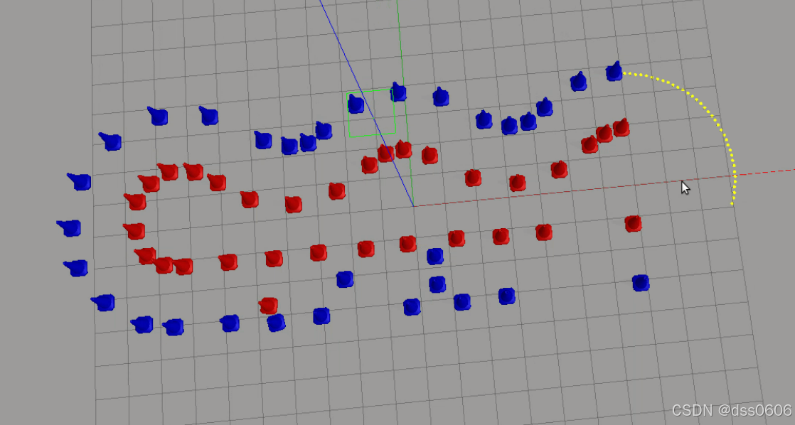
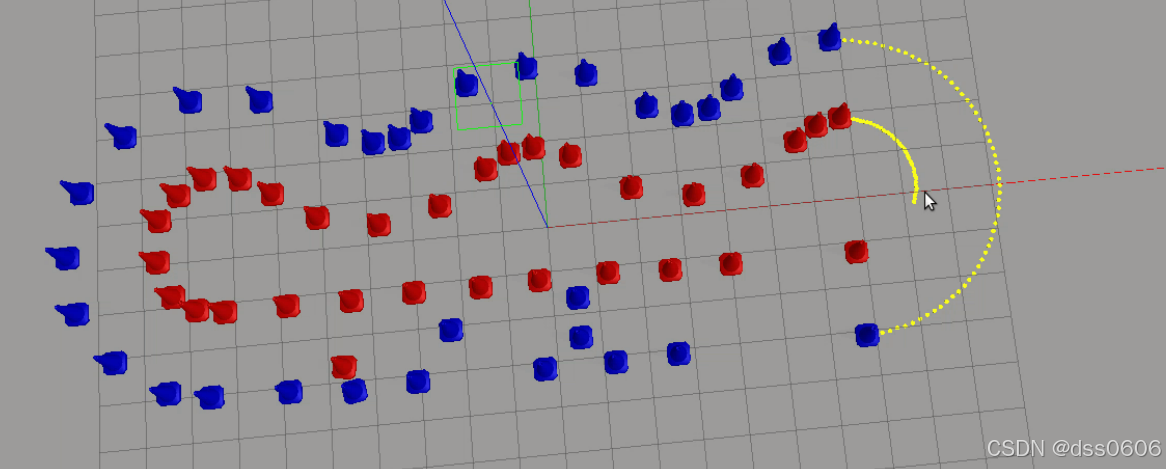
有些红绿灯的地方没有显示出来,对于黄线部分没有很好的逻辑,适应性不强,主要是通过锥桶的摆放位置来判断圆弧黄线的位置的。